Locust Rear Suspension Modifications
5 Link Design
The 4 link suspension as used on the Locust is a very popular suspension design for cars with a 'Live Axle'. It has been successfully used in many different applications. Typically, the design includes 4 equal or unequal length
control arms, a lateral locating bar, springs, and shock absorbers.
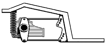
One benefit of a 4-link system is that, when the bars are of equal or near-equal length, and the front and rear mounting points are oriented such that the bars are parallel, there is a reasonably unrestricted range of vertical motion for the axle, while maintaining an efficient coupling. There will be a slight for and aft movement of the axle as it subscribes an arc.
Because each pair of links is independent of the other, the axle can "rotate" about its axis freely, allowing for roll. This means that when one wheel has to travel in a different vertical path than the other wheel e.g. over a bump, the other wheel stays in contact with the ground. This also comes into play when cornering as weight is transferred. The body rolls towards the corner as weight is transferred to the inside wheel and the distance between the body/chassis decreases and the suspension is compressed. On the other side of the car the opposite happens distance between the body/chassis and the outside wheel increases.
Lateral location
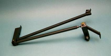
Side to side movement is normally controlled by either a Panhard rod or Watts linkage. The Panhard rod is the most popular as it is the cheapest to manufacture and easiest to fit. The 4 link suspension is often referred to as a 5 link system because of the 5th - Panhard rod link. A Panhard rod is mounted laterally between the axle, at one end, and the chassis at the other.
Typical Panhard rod assembly.
A Watts linkage is a more complex design that allows the suspension to pivot around a central point. Normally this consists of a pivot link attached to the differential with 2 links that attach to the chassis. This is the best method for lateral location of 4 link suspension systems. Unfortunately as can be seen below it is quite cumbersome and would be difficult to put into practice on a Locust.
Typical Watts linkage
So how does this affect my Locust.
I think the rear suspension on the Locust could do with some improvement. My build0 manual (JC) talks about using Triumph or Hillman Imp suspension components and setting the ride height but says nothing about the geometry. As I said above the Watts linkage is the best method of lateral location but without trying to implement that on a Locust there are a few things you can do to your rear suspension to improve things.
Springs and shock absorbers should be chosen to match the weight of the car and nature of use and the ride comfort handling requirements. In my experience you should be looking at an after market coil over shock absorber and spring combination, such as those available from Spax or AVO. With around a 14" open and 10" closed length. 160 to 230lb spring should be suitable depending on use. They should have an adjustable spring platform so ride height can be fine-tuned. I chose some Lolocost Zeemeride items with 220lb springs they fit easily but the stiffer spring meant that the ride height went up about 1" and this was too much to adjust out with the spring so the bottom mounting position may had to be re-located lower down to get the correct ride height. The advantage is that they are around half the cost of the Spax items; the disadvantage is that the shock absorbers are not adjustable, but I can live with that. The ride is comfortable but quite firm so with springs costing only £12 each I may experiment with some 180lb later.
Axle location and trailing links need to be as square to the chassis as can be achieved. This should ideally be done at build time. This may necessitate having to asymmetrically mount the axle 'C mountings' for the trailing arms or if these are already welded in place you can use a spacer on one of the rear wheels. This is also sometimes necessary to avoid the propshaft fouling the transmission tunnel.
Trailing links need to be near as parallel to each other as possible. This ensures that although the axle moves fore and aft as it rises and falls it is kept in the same relative position and does not scribe an arc. The base design of the Locust has the chassis end of the links much closer to each other than at the axle end. I think that this could be bettered by using brackets to extend the mounting locations downwards. I haven't attempted this modification yet.
The Panhard rod should be as near as parallel to the axle as possible at normal ride height. In my opinion this is one of the major faults with cars that use a Panhard rod. As the suspension is compressed the Panhard rod scribes an arc around the pivot point on the chassis. This causes sideways movement of the axle. As can be seen below the closer to parallel the lesser the lateral movement is for the same upwards movement of the axle.
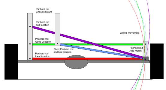
Panhard rod should also be as long as possible at between pivot points. This minimizes the amount of rear axle movement associated with the arc of the rod’s movement. The longer the rod, the larger the radius. The larger the radius, the smaller the sideways movement.
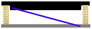
|
Panhard rod shown with exaggerated normal fitting at the normal ride height. |
|
Panhard rod shown when suspension is either compressed or (lowered and uncompressed) |
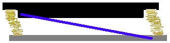
As you can see, in the second picture, as the suspension is compressed the axle is moved to the right. The larger the angle, the more lateral movement. The Locust's Panhard rod is adjustable but should only be used to maintain the static central location of the axle for example if the car's ride height is adjusted. It should not be used to try and centralise the axle this can only be done at build time.
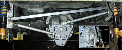
To get the Locust's Panhard rod parallel to the axle I decided that either an extension to the chassis mounting or a small tower mounting for the axle can could be made.
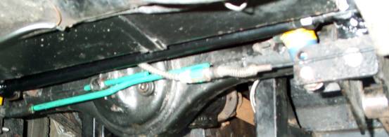
I decided to use a small tower mounting on the axle as the handbrake mechanism was in the way and would have to be modified to use the other option. The tower was fabricated from 5mm steel to slot in the void at the rear of the axle clamp on the axle. The tower was secured in place using the original Panhard rod mounting hole. The Panhard rod is now parallel to the axle and can just be seen in the photo above, ahead of the petrol tank. (The original shock absorber lower mounting holes can also be seen).
I also decided to firm up the lateral location by abandoning the Cortina bush in the Panhard rod. To do this I made up a new rod that utilises Nylaspa bushes at both ends. The bushes I used were from a Lolocost Wishbone Eye Tubes Set. The sets cost £29 for 10 eyes and bushes. The remainder may be used if I decide to experiment with the trailing arms, as these will most likely need to be shortened slightly to fit the planned new brackets. I have only done a few miles so far but I am extremely satisfied with the improvements so much so that I don't know if I will bother with the brackets and relocation of the trailing arms I may just make up some new ones that use the Nylaspa bushes.
Technical Tips
- JC Locust Build Manual
- Locust Chassis
- Locust Pedal Box
- Locust Wiring
- Locust Suspension
- Modifying a Lucas Distributor
- Cam Timing
- Mini Boot Liner Plans
- Mini Center Console Plans
- Mini Dashboard Plans
- Mini Fitting A Headlining
- MOT Check Sheet
- Spanner Sizes
- Toe Plates
My Cars
Site
- Locust build
- Locust inspiration
- Locust Update
- Mini Mayfair Restoration
- Mini City E Rebuild
- Fun
- Technical tips
- Photographs
- Fun
- Contact
External Links