Mini Flip Front
Metal Flip Front for a Mini
I have had a number of enquiries about how I made my Steel Flip Front so I thought I would fully document the process.
The
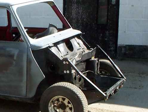
first stage of the process was to cut off the old front taking care not
to cut through any of the front loom. I was fully restoring the shell
so this was done before I started any work. I needed to replace or
repair practically every panel on the car so the flip front was the
last thing to be worked on body wise as I needed the Doors and A panels
in place as a reference point for the front panels.
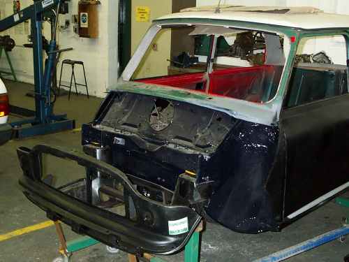
Once
the body was completed the front subframe was bolted to the shell using
metal lower rear subframe mounts and nylon upper tower bolt mounts.
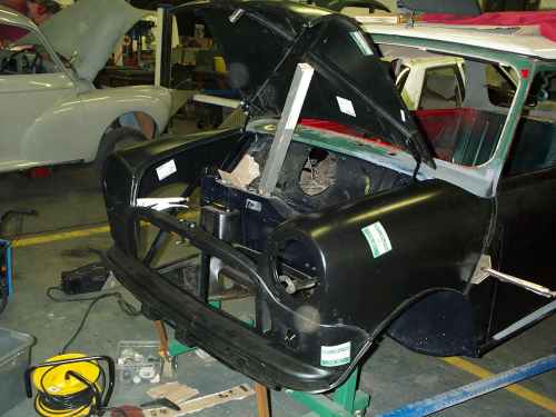
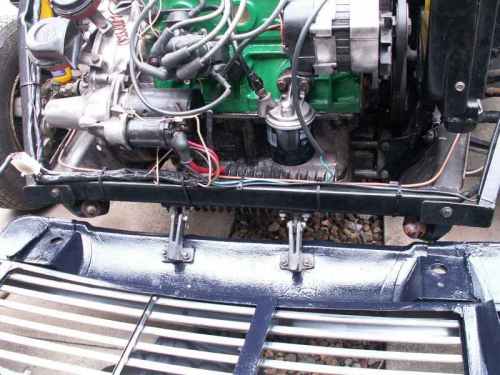
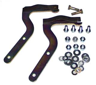
This stops any movement in the subframe. I then made up some brace
bars. These differ from the one most people use as they attach at the
top to the upper shock absorber mounts using 4 bolts of a slightly
longer length to allow the shock absorber mounts to be fitter over the
top of the brace bar. The bottom of the bar is attached to the subframe
through a hole drilled for the purpose.
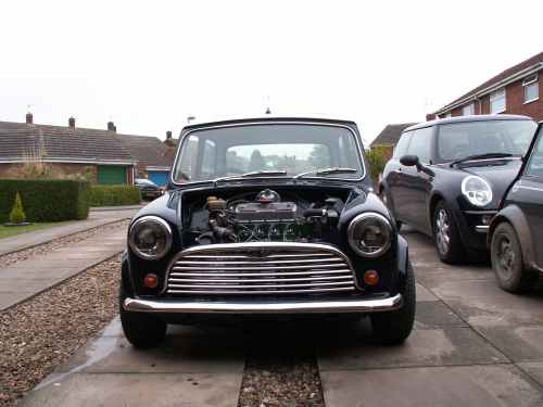
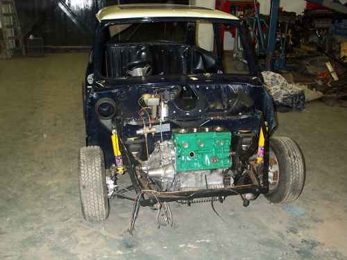
Shot of car when wheels were fitted showing brace bars
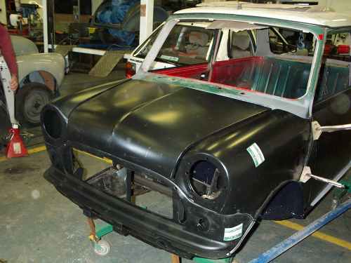
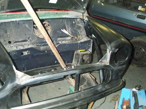
With the subframe and brace bars in place I could making the panel work.I started by bolting the front valance in place using the standard teardrop mounts this gave me a reference point to work from.
.
Front valence bolted in place.
I then clamped the wings in place this took a lot of pairs of mole grips and it involved quite a lot of patience to get the panels to line up and keep them clamped in place.
Wings clamped in place.
The bonnet was fitted using the original hinges together with the front catch to ensure that the panels were all in the correct place.
Bonnet fitted .
When I was happy with the fit the wings and valence were tack welded together strengthening fillets were welded at the front corners.
Strengthening in the corners.
A locating flange was welded on the scuttle for the wings to rest on a hole was then drilled through the wing and flange to fasten the wing in place. Linchpins and R Clips were used.
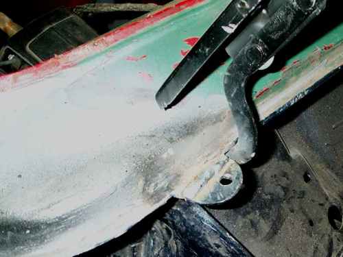
Locating flange with hole for fastening.
Top fastening in place on finished car .
Some form of hinge was required and after looking around a number of hardware shops I decided that it would be easier to make them than adapt what was available. The hinges were manufactured from a strip of steel bar. A linchpin (large clevis pin) fastened with an R clip was used as the hinge pin.
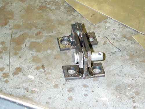
Hinge removed from car for cleaning up before painting and refitting .
The 2 parts of the hinge were made with the fingers slightly oversize and then bolted in place to the subframe and front valance before the hole for the pin was drilled. The bolts on the front valance were put through the bottom of the number plate mounting brackets as this was already double thickness so no extra reinforcement would be required
Bonnet hinged open on finished car.
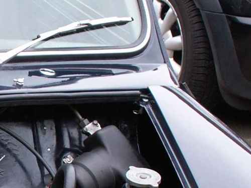
The last part of the job was to make some fastenings for the A panels to wings. I used tangs on the front wings that locate in sockets welded on to the A panels. A dimple was hammered in to the socket side to ensure a snug fit.
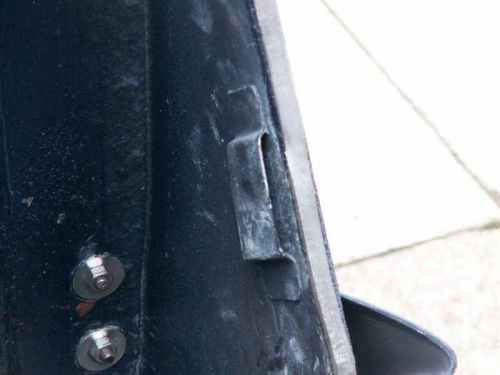
Locating socket on A panel.
Front wing tang .
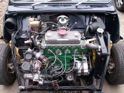
The wiring for the lights and indicators was fitted into the flip front and connected to the main loom with a multi plug to enable the front end to be fully removed. Some of the other wiring that passes across the front of the car was extended to allow it to run down the brace bar and along the front of the subframe.
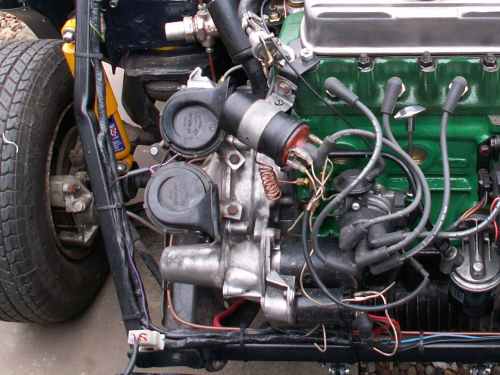
Multi plug .
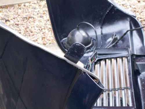
To allow the bonnet to be removed either by itself or when the front is either flipped or removed quick release bonnet hinges were fitted these were bought from Moss.
Moss Quick Release Hinge.
They are a straight replacement for the standard hinge. The standard front bonnet fastening and release was retained but supplemented with leather straps for extra safety.
Bonnet removed.
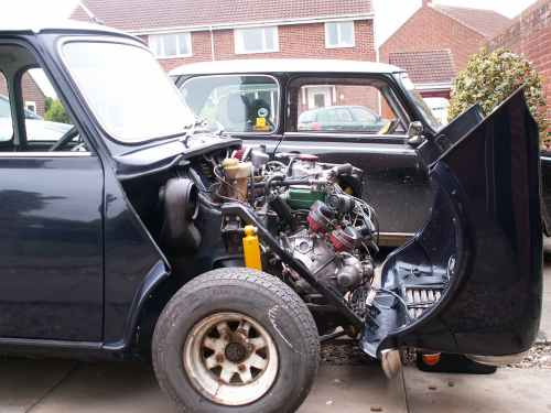
Front Flipped.
Front Flipped.
Front removed during build.
Finished car showing leather straps.
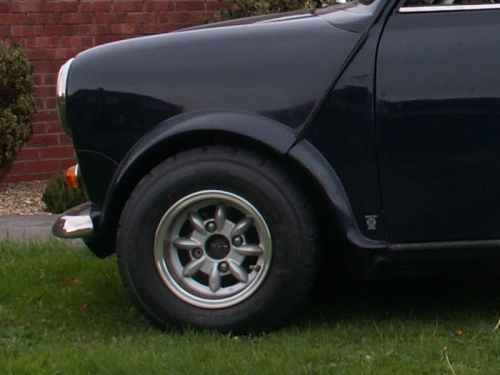
A panel join.
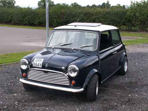
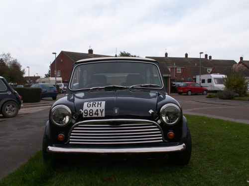
Finished car.
I hope this is of use to anyone contemplating doing a flip front conversion on a Mini.
My Mini Mayfair
Restoration
- 1 - Initial Inspection
- 2 - Boot Floor 1
- 3 - Boot Floor 2
- 4 - Boot Floor 3
- 5 - Rear Valance
- 6 - Body Stands & Engine Removal
- 7 - Front End Removal
- 8 - Bulkhead 1
- 9 - Bulkhead 2
- 10 - Sills 1
- 11 - Sills 2
- 12 - Sils 3
- 13 - Sills 4
- 14 - Footwell
- 15 - Floor
- 16 - Battery Box
- 17 - Underside
- 18 - Underside protection
- 19 - A Panels
- 20 - Wings & Front Panel
- 21 - Front Panels & Arches
- 22 - Rear Subframe
- 23 - Return From Paint
- 24 - Brakes
- 25 - Wiring
- 26 - Engine 1
- 27 - Engine 2
- 28 - Fitting Engine
- 29 - Interior, Glass, Lights
- 30 - Wheels & Tyres
- 31 - Finishing Touches